 Agriculture, grounds & landscape supplies
 Automotive, fleet parts & tires
 Building materials & construction products
 Chemicals, ingredients & raw materials
 Electrical, lighting, data & security
 Gases & welding supplies
 Industrial / MRO supplies
 IT hardware, peripherals & business technology
 Janitorial, sanitation, disposables
 Lab, scientific & research supplies
 Lubricants, fuels & petroleum products
 Material handling & warehouse supplies
 Metals & metal service centers
 Office furniture & workplace fixtures
 Office supplies, paper, ink & toner
 Packaging, shipping & mailroom
 Paint, coatings, adhesives & sealants
 Pharmaceuticals
 Plastics, resins & engineered materials
 Plumbing / PVF
 Power transmission, bearings & fluid power
 Print, labels & forms
 Restaurant equipment & supplies
 Roofing, exterior & specialty building products
 Safety & PPE
 Tools, hardware & fasteners
 Uniforms, workwear & corporate apparel
Product Details
Review product information, specifications, and procurement details.
 Back to Search Results
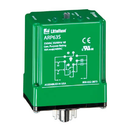
SPDT 8 Pin Alternating Relay (120V)
8-pin for alternating applications. Rotary switch allows user to lock internal relay to one specific load. The ARP Series is used in systems where equal run time for two motors is desirable. The selector switch allows selection of alternation of either load for continuous operation. LED’s indicate the status of the output relay. This versatile series may be front panel mounted (BZ1 accessory required) or 35 mm DIN rail mounted with an accessory socket. Operation Alternating: When the rotary switch is in the “alternate” position, alternating operation of Load A and Load B occurs upon the opening of the control switch S1. To terminate alternating operation and cause only the selected load to operate, rotate the switch to position “A” to lock Load A or position “B” to lock Load B. The LEDs indicate the status of the internal relay and which load is selected to operate. Note: Input voltage must be applied at all times for proper alternation. The use of a solid-state control switch for S1 may not initiate alternation correctly. S1 voltage must be from the same supply as the unit’s input voltage (see connection diagrams on datasheet). Loss of input voltage resets the unit; Load A becomes the lead load for the next operation. Specifications: Input Voltage (V): 120VAC Input Tolerance (%): -20% - 10% Input AC Line Frequency (Hz): 50/60Hz Maximum Output Voltage (V): 250VAC Output Type: Electromechanical Relay Output Form: SPDT Output Load Rating (VA): 10A resistive @ 120/240VAC and 28 VDC; 1/3hp @120 / 240VAC Isolation Voltage (V): 1500V RMS input to output Life: Mechanical - 1 x 10⁷; Electrical - 1 x 10⁶ Termination Type: Octal 8-pin Mounting Method: Plug-in socket Operating Temperature: -20° to 60°C (-4°F to 140°F) Storage Temperature (F/C): -30° to 85°C (-22°F to 185°F) Dimensions: 3.20 x 2.39 x 1.78 in. (81.3 x 60.7 x 45.2mm)
Your Price
Contract Pricing
Product Overview
8-pin for alternating applications. Rotary switch allows user to lock internal relay to one specific load. The ARP Series is used in systems where equal run time for two motors is desirable. The selector switch allows selection of alternation of either load for continuous operation. LED’s indicate the status of the output relay. This versatile series may be front panel mounted (BZ1 accessory required) or 35 mm DIN rail mounted with an accessory socket. Operation Alternating: When the rotary switch is in the “alternate” position, alternating operation of Load A and Load B occurs upon the opening of the control switch S1. To terminate alternating operation and cause only the selected load to operate, rotate the switch to position “A” to lock Load A or position “B” to lock Load B. The LEDs indicate the status of the internal relay and which load is selected to operate. Note: Input voltage must be applied at all times for proper alternation. The use of a solid-state control switch for S1 may not initiate alternation correctly. S1 voltage must be from the same supply as the unit’s input voltage (see connection diagrams on datasheet). Loss of input voltage resets the unit; Load A becomes the lead load for the next operation. Specifications: Input Voltage (V): 120VAC Input Tolerance (%): -20% - 10% Input AC Line Frequency (Hz): 50/60Hz Maximum Output Voltage (V): 250VAC Output Type: Electromechanical Relay Output Form: SPDT Output Load Rating (VA): 10A resistive @ 120/240VAC and 28 VDC; 1/3hp @120 / 240VAC Isolation Voltage (V): 1500V RMS input to output Life: Mechanical - 1 x 10⁷; Electrical - 1 x 10⁶ Termination Type: Octal 8-pin Mounting Method: Plug-in socket Operating Temperature: -20° to 60°C (-4°F to 140°F) Storage Temperature (F/C): -30° to 85°C (-22°F to 185°F) Dimensions: 3.20 x 2.39 x 1.78 in. (81.3 x 60.7 x 45.2mm)
Full Specifications
Procurement Details
Documents
Related / Comparable Items
| Product | MPN | Description | Availability | Unit | Your Price |
|---|---|---|---|---|---|
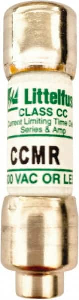
| CCMR.500T | Cartridge Time Delay Fuse: CC, 0.5 A, 1-1/2" OAL, 0.41" Dia 20 kA at DC, 200 (RMS) & 300 (Self-Certi ... | ● In Stock | PR |
$0.00 / PR
|
|
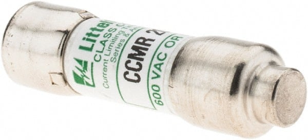
| CCMR020.T | Cartridge Time Delay Fuse: CC, 20 A, 1-1/2" OAL, 0.41" Dia 20 kA at DC, 200 (RMS) & 300 (Self-Certif ... | ● In Stock | PR |
$0.00 / PR
|
|
| CCMR012.T | Cartridge Time Delay Fuse: CC, 12 A, 1-1/2" OAL, 0.41" Dia 20 kA at DC, 200 (RMS) & 300 (Self-Certif ... | ● In Stock | PR |
$0.00 / PR
|
|
| KLDR17.5 | Cartridge Time Delay Fuse: CC, 17.5 A, 1-1/2" OAL, 0.41" Dia 20 kA at DC & 200 kA at AC, Melamine | ● In Stock | PR |
$0.00 / PR
|
|
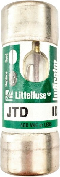
| 0JTD020.TXID | Cartridge Time Delay Fuse: J, 20 A, 2-1/4" OAL, 13/16" Dia 20 kA at DC & 200/300 kA at AC, Melamine | ● In Stock | PR |
$0.00 / PR
|